Circuit Simplification
(Content adapted from Critchlow & Eck)
As noted above, a physical circuit does have some dependence on time, since each device in the circuit requires a non-zero time to respond to a change in its inputs. A more precise model needs to take these delays into account—a circuit is modeled by a Boolean expression plus a set of delay factors (other cost measures may also be important: power consumption, heat production, area occupied, etc., but we will focus on the delay issue here). We will make the simplifying assumption that all gates have the same delay time, so we will measure the total delay of a circuit in terms of the number of gate delays required before the output values accurately reflect a change to the input values.
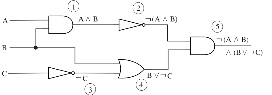
Given a combinational circuit, we may compute the delay, also known as the span, by finding the number of gates on the longest path (the critical path) from an input to an output. For example, the circuit in the figure below has a span of three gate delays, with the critical path passing either through the AND, NOT, AND sequence along the top, or through the NOT, OR, AND along the bottom. Note that this is a conservative estimate of the delay required, although for certain inputs the output may become stable sooner—for example, if the input changes from 0 to 1 while is 0, then after one gate delay the output of the OR will become 1; since the output of the upper NOT was already 1 in this case (why?), the final output will settle at 1 after only two gate delays. However, other combinations of inputs may well take the entire three gate delays to correctly determine the value of the output.
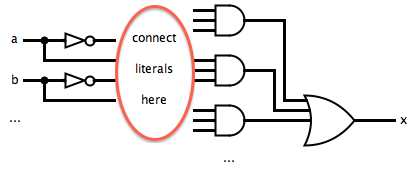
One approach to reducing the delay of a circuit is to use the disjunctive normal form, also known as the sum-of-products. Since an expression in DNF is the OR of a collection of terms which are the AND of some number of simple terms, and a simple term is either an input or a negated input, the corresponding circuit can be constructed in three layers:
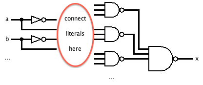
An interesting property of the sum-of-products representation falls out of the De Morgan laws. Since , the two layers of AND and OR gates may be replaced entirely with NAND gates to get an equivalent circuit!
Unfortunately, this does not mean that any Boolean expression can be computed by a circuit with only three gate delays. One problem comes when we need AND and OR gates (or NAND gates) with more than two inputs—in general, with input variables, there may be AND gates that need inputs, and there could be on the order of gates in the AND level, requiring an OR gate with that many input lines. We will see in the next section how to build gates with a larger number of inputs out of gates with just two inputs, at the cost of an increased gate delay.
Karnaugh Map
Another problem with DNF comes if we use the full DNF expression extracted from a truth table. If we use the DNF Theorem to produce an expression from the truth table for the implication , we will get . However, we may use Boolean algebra identities to find an equivalent DNF expression, (which only needs two gate delays, since the AND layer disappears). There are general techniques for finding simpler DNF expressions such as this; we will look at a straightforward technique called a Karnaugh map, although for computer implementation the related Quine-McCluskey algorithm is better (and for large numbers of input variables a heuristic approach is necessary).
A Karnaugh map is a way of visualizing entries in a truth table so that adjacent entries only differ on the value of one input variable. For example, the entry for will be next to the entry for . If adjacent entries each contain 1, meaning that those terms would participate in the full DNF expression, then they may be replaced by a single term with just the variables that are the same: in the example, this corresponds to the simplification .
For two input variables, a Karnaugh map is a array:
This is just a compact rearrangement of the truth table:
However, note that the adjacent cell condition is true: horizontally adjacent cells only differ on , while vertically adjacent cells only differ on .
Once we have laid out the Karnaugh map, a simplified expression may be read off by finding a way to cover all of the 1's in the map with "implicants." An implicant is a rectangle whose side lengths are a power of 2; it corresponds to finding a collection of adjacent cells in the map (all of which contain 1) that all agree on some of the input literals and that collectively include all combinations (negated or not) of the other input variables. The resulting term for an implicant is just the product of the common literals among all the cells covered by the implicant.
On a map, the only implicants are individual cells (), a row (), a column (), or the entire map (). The cells correspond to terms such as , the rows are either or , the columns are either or , and the entire map is (the empty product). To get the simplest expression, we want to take the fewest number of the largest possible implicants that between them cover all of the 1's in the map. Implicants may overlap, as long as all of (and only) the 1's are covered by at least one implicant.
Here is the example again. First the truth table for :
As a Karnaugh map, this is:
The best way to cover this map with implicants is to take the first row and the second column. That gives the simplified terms and , so the final simplified expression is . Here is the map with the implicants outlined:

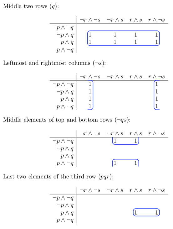
A Karnaugh map can also work with three or four input variables, producing either a or a array. The same procedure applies, with three complications: \begin{enumerate} \item To satisfy the adjacent cell condition, successive rows or columns must change only one variable at a time: for example, the rows might be labelled in order , , , and ; \item Implicants may be 1, 2, or 4 rows tall by 1, 2, or 4 columns wide; and \item Implicants may "wrap around" from one side of the map to the other. \end{enumerate} For example, on a map, one possible implicant is the middle two rows; another is the leftmost and rightmost columns (wrapping horizontally); a third is the block consisting of the middle two elements of the top row and the middle two elements of the bottom row (wrapping vertically); a final example is the last two elements of the third row:
Don't Care Values
A Karnaugh map also allows us to find simple circuits in the case that some combinations of inputs will never occur, so that we do not care what the output is in those rows of the truth table. By entering a don't care value, such as X, in the map, we have the freedom to either ignore or include those cells when covering the map with implicants; by including a cell with an X along with a group of 1's, we might be able to construct a larger (and hence simpler) implicant.
For example, suppose we have the following truth table for a four-variable Boolean expression (this represents the inputs that are binary numbers less than ten and divisible by three):
As a Karnaugh map, this is:
The 1's, plus some of the X's, may be covered by four implicants: , , , and . Note that the second implicant wraps around from the third cell on the top row to the third cell (with an X, which is also covered by the implicant) on the bottom row; if it were just the 1 on the top row, then the term would be , which is not as simple. Here are the cells that end up being covered:
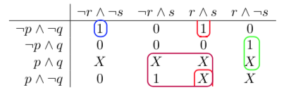
Therefore, the simplified expression is . This may be computed by the following circuit:
In the next section, we will see how to implement this with a total delay of 5, using only two-input AND and OR gates.
Exponential Blowup
The final difficulty with building low-delay circuits from DNF expressions is that, even with the simplification provided by something like a Karnaugh map, many Boolean functions lead to an exponential blowup when expressed in DNF. In the worst case, an expression with input variables may require terms in a sum-of-product representation—consider the case of a Karnaugh map where the 1's are in a checkerboard arrangement, so that none are adjacent. When is large enough, it might not even be practical to consider the truth table at all; for example, a circuit that can add two 32-bit numbers requires 64 input lines, which would lead to a truth table with entries. The next section will also discuss approaches to this kind of problem.
Exercises
For each of the following Boolean expressions, compute the total delay of the direct translation of the expression into a circuit.
Answer
The longest path has four gate delays.
Answer
The longest path has five gate delays.
Answer
The longest path has four gate delays.
For each of the expressions in the previous problem, use a Karnaugh map to find an equivalent sum-of-products expression, and draw the resulting circuit.
Answer
The expression is a tautology, so an equivalent sum-of-products expression is .
The expression is true everywhere except , so an equivalent sum-of-products expression is .
The expression is true when at least three of the inputs are true, so an equivalend sum-of-products expression is .
Suppose we want to build a counter that cycles through the numbers 0, 1, 2, 3, 4, and back to 0. One element of this counter will be a circuit that takes the current number, expressed in binary, and outputs the next number. Here is the truth table for this function, with three inputs (, , and ) and three outputs (, , and ):
Since the counter should never reach numbers 5, 6, or 7, we do not care about the output when is 101, 110, or 111. Use Karnaugh maps to find a simple circuit for this function.
Answer
The only case where we need to be true is when is true. Similarly, must be true when is true. Finally, is true when is true, or :
In binary-coded decimal (BCD), four bits are used to represent the numbers 0 (0000) through 9 (1001); the other six bit patterns (1010 through 1111) are unused. BCD is often used in circuits where decimal numbers need to be displayed; a common device for doing so is the seven-segment display. Using only seven elements (for example, light-emitting diodes), we may form a reasonable approximation of all the digits 0--9:
Construct a truth table with four inputs and seven outputs showing how to produce these characters from input in BCD (be sure to include a diagram indicating which output column corresponds to which display element). Use Karnaugh maps to design a relatively simple circuit that implements a seven-segment decoder.
Answer
See a solution at CircuitVerse
An exercise in the Circuits section examines conjunctive normal form (CNF), the dual of DNF. Explore what kind of circuits result from CNF, and how to extract a simplified CNF expression from a Karnaugh map (Hint: look at blocks of 0's.).