State Machines
In another section1 we learned about Moore machines, a version of finite state automata where there is an output associated with each state. Using flip-flops, we can build a circuit that implements a Moore machine. Here is a block diagram for such a circuit (although the connections are shown as single wires, all but the clock may be several bits wide):
In addition to the feedback within each flip-flop, there is a larger-scale feedback loop of the current state back to provide input for the next step. The box labelled Comb. Logic is a combinational circuit with two functions: compute an output based on the current state, and compute the next-state control signals based on the input and the current state. The box labelled State is one or more flip-flops; when a clock pulse arrives, it takes the control signals from the combinational logic and advances to the next state—the state of the machine is simply the current states of these flip-flops.
If there are flip-flops, each of which can be 0 or 1, then the machine can be in different states. Therefore, if our Moore machine needs states, we will need at least flip-flops. One step in designing the circuit for a given machine will be to assign a binary encoding to each state. For example, if the machine has three states, , , and , then we will need two flip-flops. The circuit state will be the combination of the flip-flop outputs: . Given this, we may arbitrarily choose the encoding , , and (and the state will go unused).
Although the diagram shows the combinational logic has both the machine input and the current state available to compute the output, the convention in a Moore machine is that only the state is used to determine the output. There is a practical reason for this: during a clock cycle, as soon as the current state has propagated through the logic gates, we want the output to be available and stable. The input signals may not be stable until close to the end of the cycle (just before they are needed to determine the next state), and we would prefer not to see "glitches" in the output while the input might still be changing.
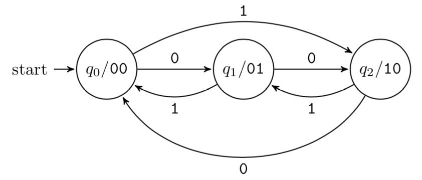
Here is an example of this process. Consider the following state machine for a mod-3 up/down counter:

It has one input, which will be read once per clock pulse; call it . When is 0, each clock pulse increments the counter through the states , , , and back to . When is 1, it decrements. At each state, the output is the corresponding number in binary: 00, 01, and 10.
We will use two D flip-flops, and the obvious encoding of states to bit patterns (which also happens to be the mapping from state to output, so we can just use the current state, 00, 01, or 10, to drive the output directly).All that remains is to design the combinational circuit that computes the and flip-flop control signals based on the input and current state. For this, we will first fill in a truth table with current state, input, and desired next state values, then use the excitation table for the flip-flops to decide an appropriate signal (for type-D flip-flops, this is particularly easy, since the required input is just the next state ):
current | input | next | control | |||
|---|---|---|---|---|---|---|
0 | 0 | 0 | 0 | 1 | 0 | 1 |
0 | 0 | 1 | 1 | 0 | 1 | 0 |
0 | 1 | 0 | 1 | 0 | 1 | 0 |
0 | 1 | 1 | 0 | 0 | 0 | 0 |
1 | 0 | 0 | 0 | 0 | 0 | 0 |
1 | 0 | 1 | 0 | 1 | 0 | 1 |
Here is the Karnaugh map for :

And here is the map for :

Therefore, simple DNF expressions for the control signals are and . The full circuit for the counter is therefore:
With combinational circuits to perform arithmetic and logic operations on data, plus registers to store intermediate results and keep track of program steps, a sequential circuit allows us to model an entire central processing unit. By connecting the inputs and outputs to external storage and I/O devices, the CPU forms the core of a general-purpose computer; details are left to the reader.
Exercises
Design a BCD accumulator whose input is a three-bit two's complement number representing the value to be added to the total. That is, the state will be a decimal digit 0–9, represented in binary (0000 through 1001). The output should be the signal lines to drive a seven-segment display (see Exercise 4 of the Circuit Simplification section). If the input is 000, then the state will be unchanged. If the input is +1 (001) through +3 (011), then that number will be added on each clock pulse. If the input is -4 (100) through -1 (111), then the total will go down by that amount on each pulse.
Reinterpret the block diagram for a Moore machine to produce a Mealy machine, where an output is associated with each transition. That is, the output should be determined by the current state and the input. What might happen to the output if the input changes during a clock cycle? Compare this behavior to a Moore machine.
- Not yet written….↩